CIRC
08
.:Twisting:.
.:Potentiometers:.
(ARDX) .:Arduino Experimentation Kit:. (ARDX)
What We're Doing
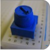
Along with the digital pins, the Arduino also has 6 pins which can be used for analog input. These inputs take a voltage (from 0 to 5 volts) and convert it to a digital number between 0 (0 volts) and 1023 (5 volts) (10 bits of resolution). A very useful device that exploits these inputs is a potentiometer (also called a variable resistor). When it is connected with 5 volts across its outer pins the middle pin will read some value between 0 and 5 volts dependent on the angle to which it is turned (ie. 2.5 volts in the middle). We can then use the returned values as a variable in our program.
The Circuit
The Parts
| CIRC-08 Breadboard Sheet x1 |
2 Pin Header x4 |
Wire | Wire | ||||
| Green LED x1 |
560 Ohm Resistor Green-Blue-Black-Black x1 |
||||||
Schematic
Resources
.:download:.
Breadboard layout sheet
http://ardx.org/BBLS08
Fritzing diagram
https://wcrsyyc.github.io/ardx/fritzing/CIRC08.fzz
.:view:.
assembly video
http://ardx.org/VIDE08
Code (no need to type everything in just)
File > Examples > 3.Analog > AnalogInput
(example from the great arduino.cc site, check it out for other ideas)
/*
  Analog Input
 Demonstrates analog input by reading an analog sensor on analog pin 0 and
 turning on and off a light emitting diode(LED)  connected to digital pin 13.
 The amount of time the LED will be on and off depends on
 the value obtained by analogRead().

 The circuit:
 * Potentiometer attached to analog input 0
 * center pin of the potentiometer to the analog pin
 * one side pin (either one) to ground
 * the other side pin to +5V
 * LED anode (long leg) attached to digital output 13
 * LED cathode (short leg) attached to ground

 * Note: because most Arduinos have a built-in LED attached
 to pin 13 on the board, the LED is optional.


 Created by David Cuartielles
 modified 30 Aug 2011
 By Tom Igoe

 This example code is in the public domain.

 http://arduino.cc/en/Tutorial/AnalogInput

 */

int sensorPin = A0;    // select the input pin for the potentiometer
int ledPin = 13;      // select the pin for the LED
int sensorValue = 0;  // variable to store the value coming from the sensor

void setup() {
  // declare the ledPin as an OUTPUT:
  pinMode(ledPin, OUTPUT);
}

void loop() {
  // read the value from the sensor:
  sensorValue = analogRead(sensorPin);
  // turn the ledPin on
  digitalWrite(ledPin, HIGH);
  // stop the program for <sensorValue> milliseconds:
  delay(sensorValue);
  // turn the ledPin off:
  digitalWrite(ledPin, LOW);
  // stop the program for for <sensorValue> milliseconds:
  delay(sensorValue);
}
Not Working? (3 things to try)
Sporadically Working
This is most likely due to a slightly dodgy connection with the potentiometer's pins. This can usually be conquered by taping the potentiometer down.
Not Working
Make sure you haven't accidentally connected the potentiometer's wiper to digital pin 0 rather than analog pin 0. (the row of pins beneath the power pins)
Still Backward
You can try operating the circuit upside down. Sometimes this helps.
Making it Better?
Threshold Switching:
Sometimes you will want to switch an output when a value exceeds a certain threshold. To do this with a potentiometer change the loop() code to.
void loop() {
  int threshold = 512;
  if(analogRead(potPin) > threshold){ digitalWrite(ledPin, HIGH);}
  else{ digitalWrite(ledPin, LOW);}
}
This will cause the LED to turn on when the value is above 512 (about halfway), you can adjust the sensitivity by changing the threshold value.
Fading:
Lets control the brightness of an LED directly from the potentiometer. To do this we need to first change the pin the LED is connected to. Move the wire from pin 13 to pin 9 and change one line in the code.
int ledPin = 13; ----> int ledPin = 9;
Then change the loop code to.
void loop() {
  int value = analogRead(potPin) / 4;
  analogWrite(ledPin, value);
}
Upload the code and watch as your LED fades in relation to your potentiometer spinning. (Note: the reason we divide the value by 4 is the analogRead() function returns a value from 0 to 1023 (10 bits), and analogWrite() takes a value from 0 to 255 (8 bits) )
Controlling a Servo:
This is a really neat example and brings a couple of circuits together. Wire up the servo like you did in CIRC-04, without changing the potentiometer wiring. Then open the example program Knob (File > Examples > Library-Servo > Knob ), upload to your Arduino and watch the servo shaft rotate as you turn the potentiometer.